
I hope to accomplish with this text a simple endevour that I wanted to write for about a few months: I want to explain in very simple lines how computer graphics works in simple terms. There will be some math, but don’t worry: I want to make this the most didatical I possibly can. I hope you tag along this journey through computer graphics and endup finding yourself amazed by it too.
We going to start with just a single function that put a pixel color in a position of the screen. And from there, I’m going to explain how we going to “project” tridimensional images onto the screen. We going to aproach this challenge starting by the most straight forward method first: Raytracing. Which means we going to do exactly what light does, but, in reverse. It may sound weird at first, but trust me: it is pretty simple. So buckle up, and lets get started!
Where we are going to draw
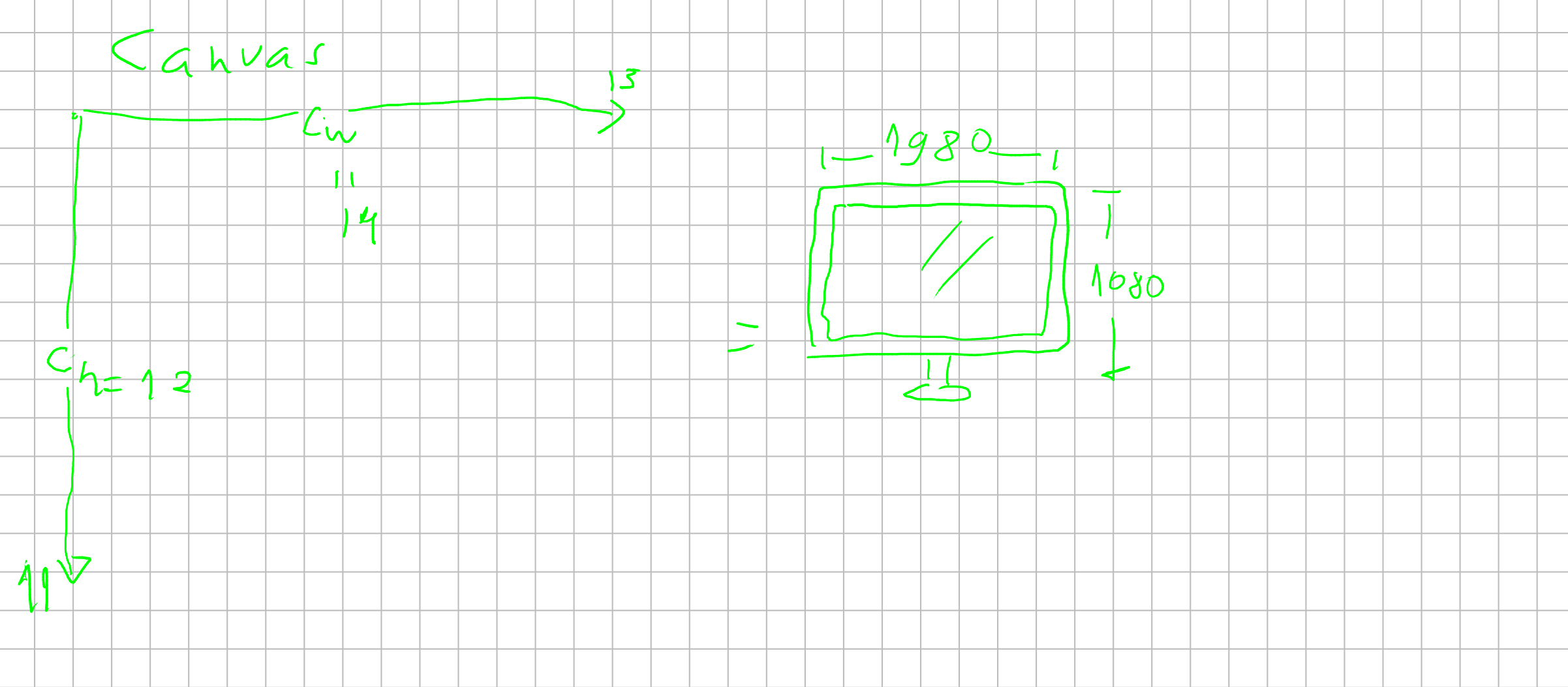
So lets call the place where we draw colors “canvas”. The computer screen is just an matrix of pixels, which are, in the standard RGB model, sum of the three component colors: Red, Green and Blue.
You could visualize the screen as :
So we are going to start by using an method canvas.putPixel(positionX, positionY, color) which is going to put a pixel at an specified position with a particular color.
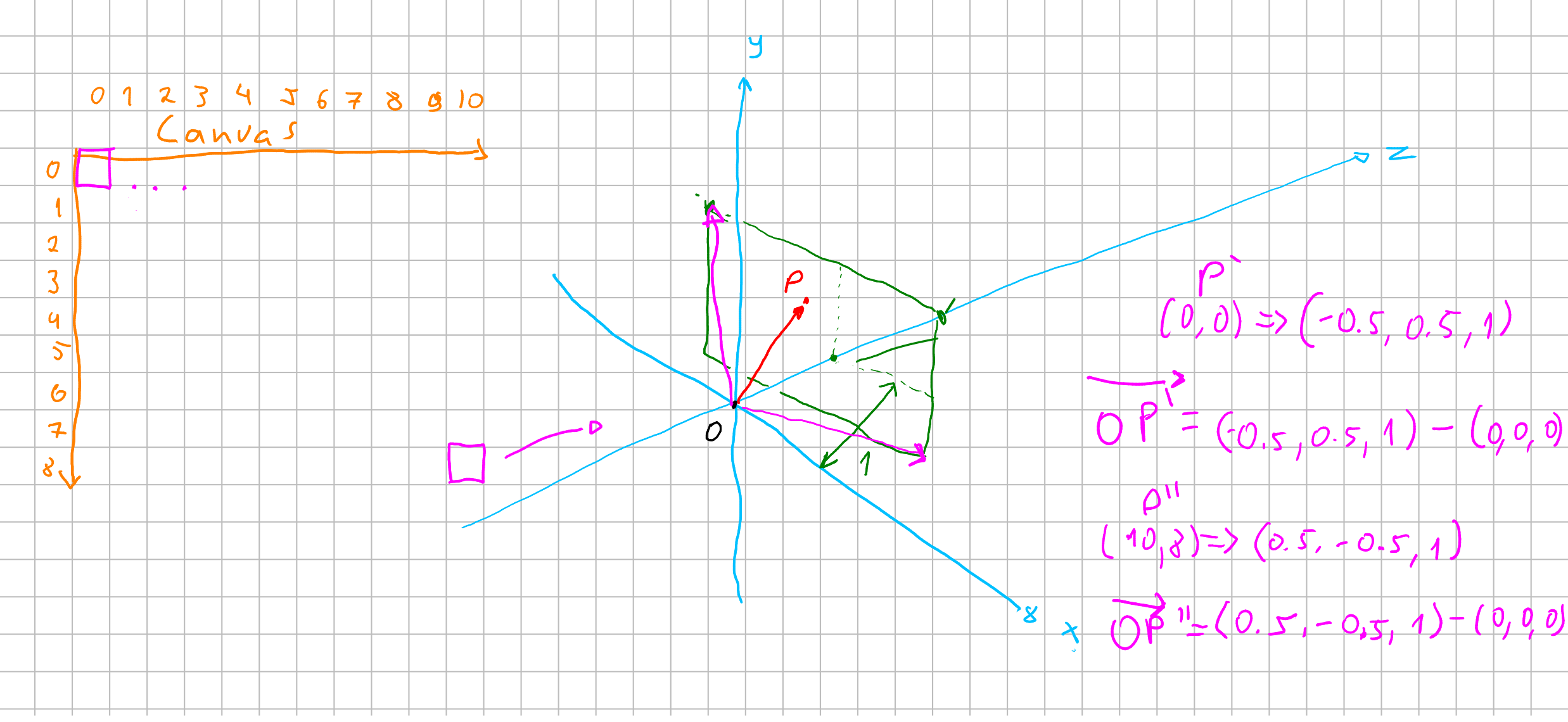
But we must understand that, because the canvas works as an matrix, the way we access it is not like an cartesian map. (0,0) it’s not the center of the screen, but the top left corner of the canvas.
Usually graphic developers want to work with a cartesian representation of the screen because its easier to wrap his mind around it. We can think about this translation as an map, which we want our putPixel() procedure to do for us.
![]() Which if you think about is pretty simple: we want that when we call
Which if you think about is pretty simple: we want that when we call putPixel(x,y, color) with (x: 0, y:0) to write a pixel in the center of the screen instead of its top-left corner.
As in the image above, you can notice that we have to change the diretion on the \(y\) axis and divided it by half. And in \(x\) axis, just dividing by half is enough to get it right.
I propose this “translation” here already to get you familiar with the many translations we going to do during this text.
How we going to draw anything?
With our blade called putPixel we are now ready to start drawing on the screen. But how can we draw tridimensional figures onto the screen?
Well, lets think about how the light works for a second.
A light source emits light that hit a surface and it is reflected all the colors which are not absorbed (duh!), and those reflected rays reach your eyes and then inform your brain.
We could write an algorithm that archieved the same beharviour, but you can imagine that a simple lightbulb emmit around \(5.5 \times 10^{32}\) fotons per second. A commom processor can peak around \(3.0 GHz\) which means \(3 \times 10^9\) instructions executed each second. Even though it may seem a big number, it is a tiny number in comparisson to the number of fotons a simple lightbulb can emmit.
So, simulating light that way is not feasible for the current technology. So, how else can we simulate that?
Well … Let’s do it in reverse! Imagine that we want actually, to cast just the lightrays that reach our eyes. Then, imagine lightrays leaving your eyes, and reaching the object and then reaching the lightsource. We just need those rays. That would be raytracing!
So how can we archieve that? We need then to think about how we are going to cast those rays in tridimensional space and how to translate that to our screen.
Imagine that we are painters: We have a canvas in front of us. And imagine that this canvas is “discrete”. By discrete I mean: this canvas is a grid, where in each position you can put just one color. To draw onto this canvas the image behind it you would then look at each grid cell and see what color correspond to it, and then put the color onto the canvas. And after repeating that for every cell you would have a “discrete” picture of what you decided to paint. We want to replicate this tecnique here.
We want to create a tridimensional space and then translate it to our bidimensional discrete screen.
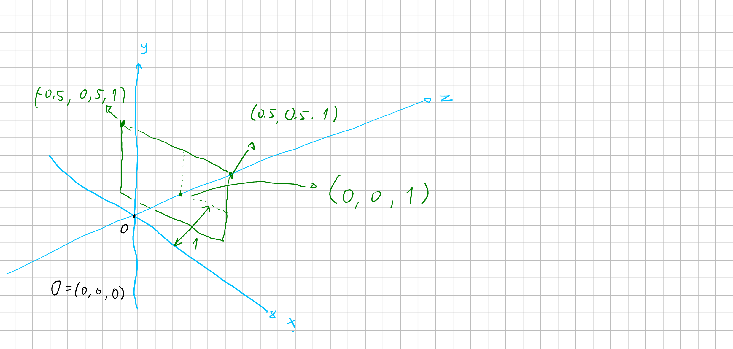
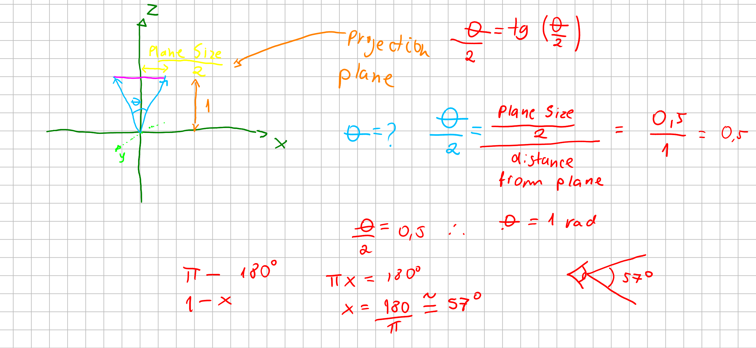
Let’s imagine our cartesian coordinate system with three axis: \((x, y, z)\) we are all familiar from school. Imagine your eye is at the origin \(O(0,0,0)\). In order to replicate the painter’s canvas, we want a plane \(P\) to know “where” we are looking at the color. So imagine that this plane is at one unit distant from our eyes.
What then we want to archieve is: we want somehow to cast a line from the origin to specific points of our plane \(P\) and see where it lands. If it lands at anything we, for now, want to know its color.
A plane at one unit distant from our eyes, means that we have aproximatly \(57\) degrees of field of view.
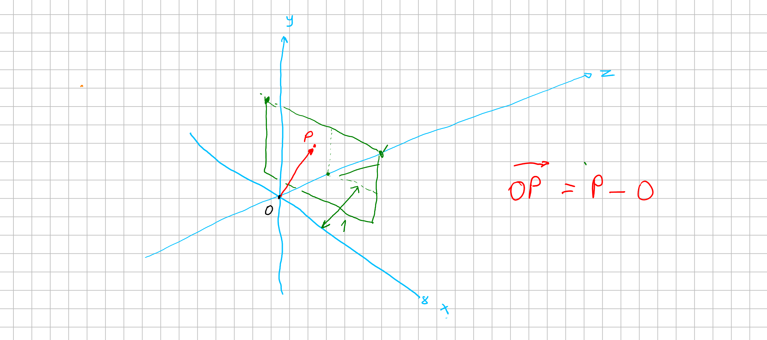
Now to get a vector from our origin to a specified position at \(P\), lets assume we have an way to map a position from our screen to a point \(p = (x, y, z)\) at \(P\). With that point we can calulate an vector from our origin \(O\) to that point \(p\) with \(\vec{v} = p - O = (x, y, z) - (0, 0, 0) = (x, y, z)\). Now we have a vector that goes from the origin through the plane \(P\). This vector is our “foton”. We can think of an scalar \(\lambda\) which \(\lambda \vec{v}\) would describe our foton streching across our world.
But how can we know if this foton has colided with something?
Calculate hit!
Currently most of tridimensional objects are meshes of triangles.
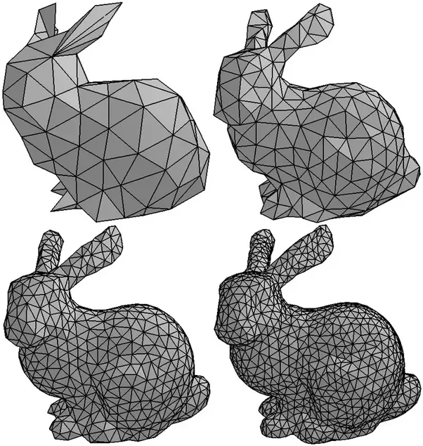
So in order to render this tridimensional bunny, we would have to calculate if our ray \(\lambda \vec{v}\) hited one of the surfaces of a triangle. This would mean a solution of an equation of “line to surface”.
To ilustrate that, we going to start by showing an simpler example by collinding with an sphere. An sphere is easier to define than a mesh of triangles, at least for now. To define it, we need one simple equation to define a sphere.
Then, to check if a collision of our foton with our sphere happened, we just have to find our scalar \(\lambda\) that make the position of our \(\vec{v}\) equals to a point of our sphere. In other words: we want a solution to find a root that gives us a point in the sphere.
Let’s be a bit mathy
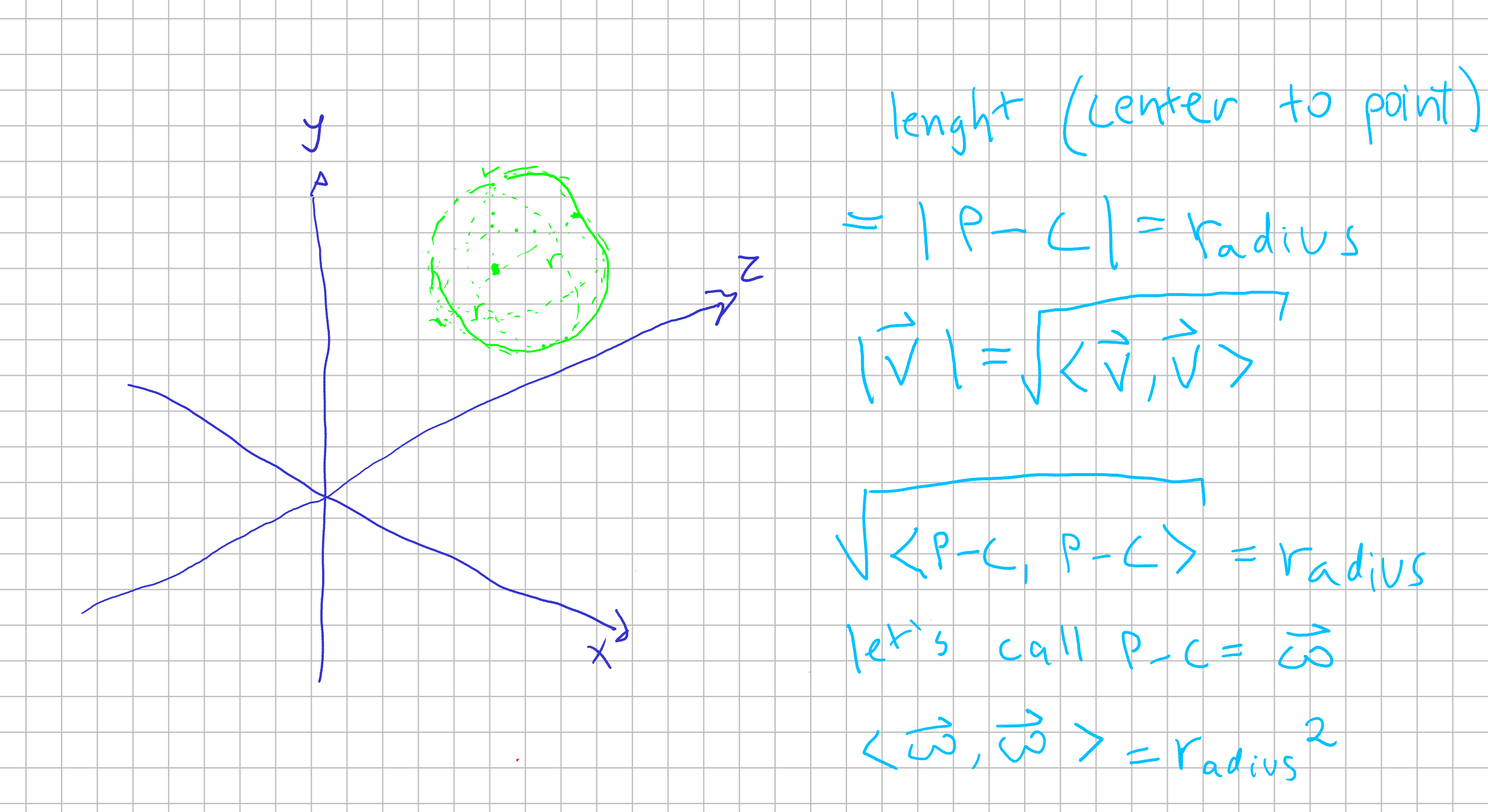
We define a sphere as an structure where all points have the same distance from the center. This distance we call it radius. \(distance(all points, center) = radius\)
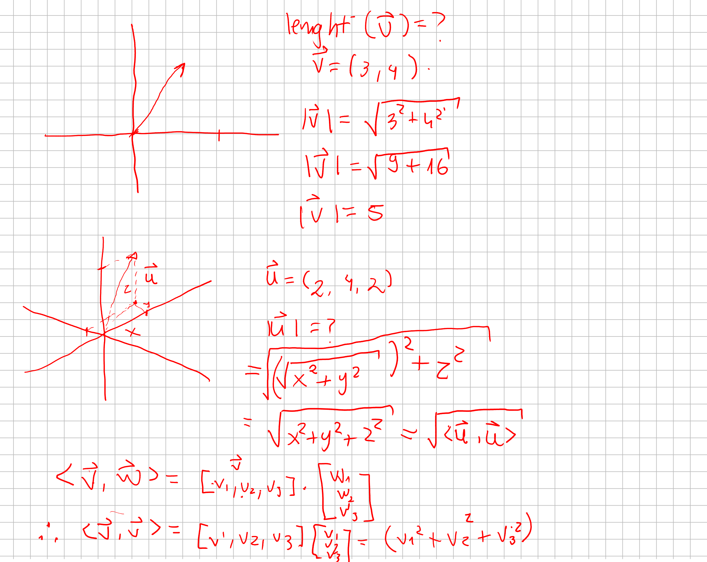
As you can see, we can describe the lenght of a vector \(\vec{u} = (x, y, z)\) as \(|\vec{u}| = \sqrt{x^2 + y^2 + z^2} = \sqrt{<\vec{u} , \vec{u}>}\). Given that definition, we can define an sphere such as given a center \(C\) a sphere is a set of points \(P\) which are in a distance of a radius \(r\).
So that being said, we now have an equation which tell us our “ray” cast from our origin from a pixel in a screen. Then, we now have an equation to a sphere in our world. Every information is given, so we just need to compute what value to \(\lambda\) such as our ray \(\lambda \vec{v}\) is equal to a point in our sphere.
Then we want to find a point where it is both in line and in the circunference. So we substitue \(P\) in our sphere equation with our ray equation.
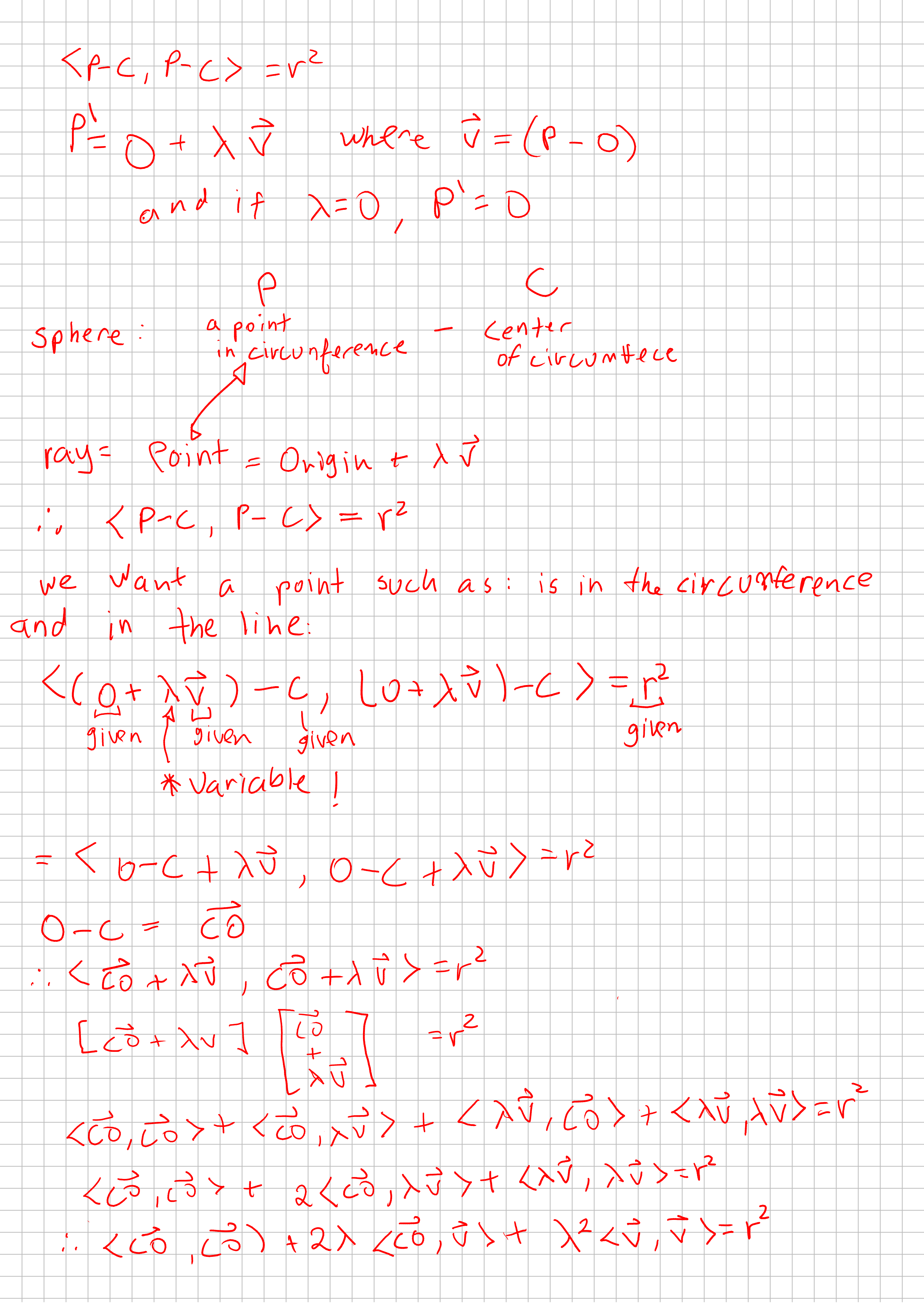
That geometricly makes sense! Because we can have a tangent line, a ray that crosses the sphere and therefore would cross two points, and we could have none intersection.
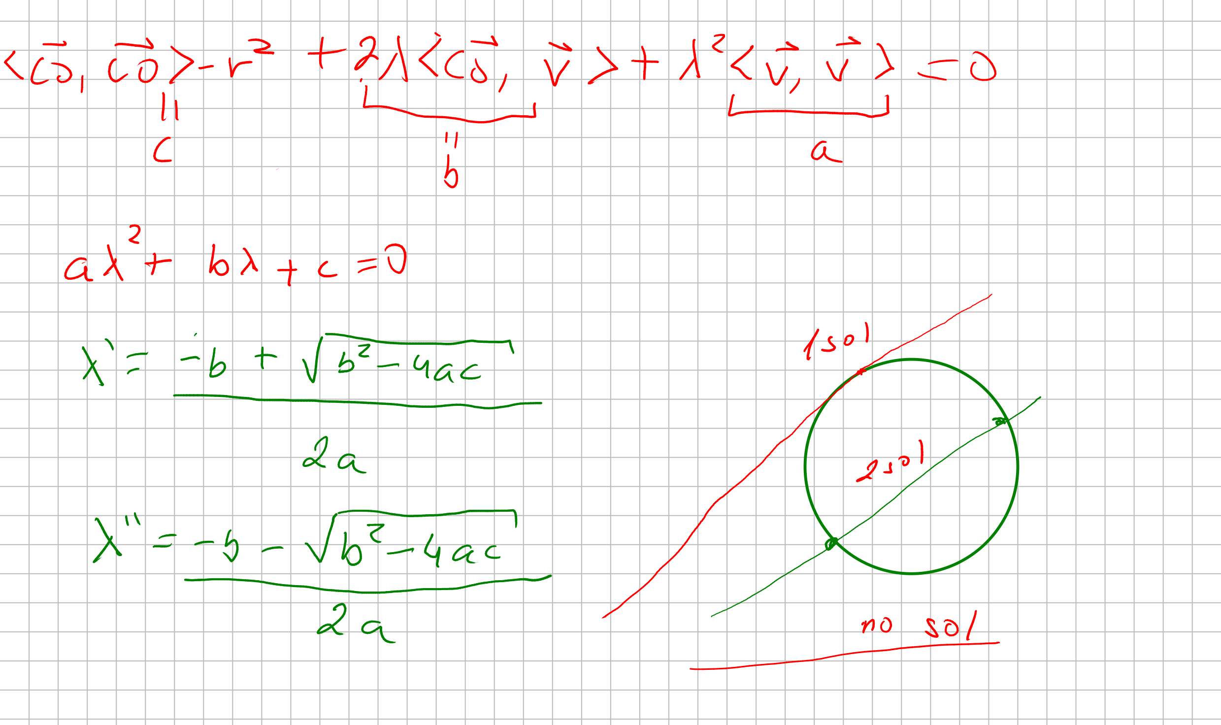
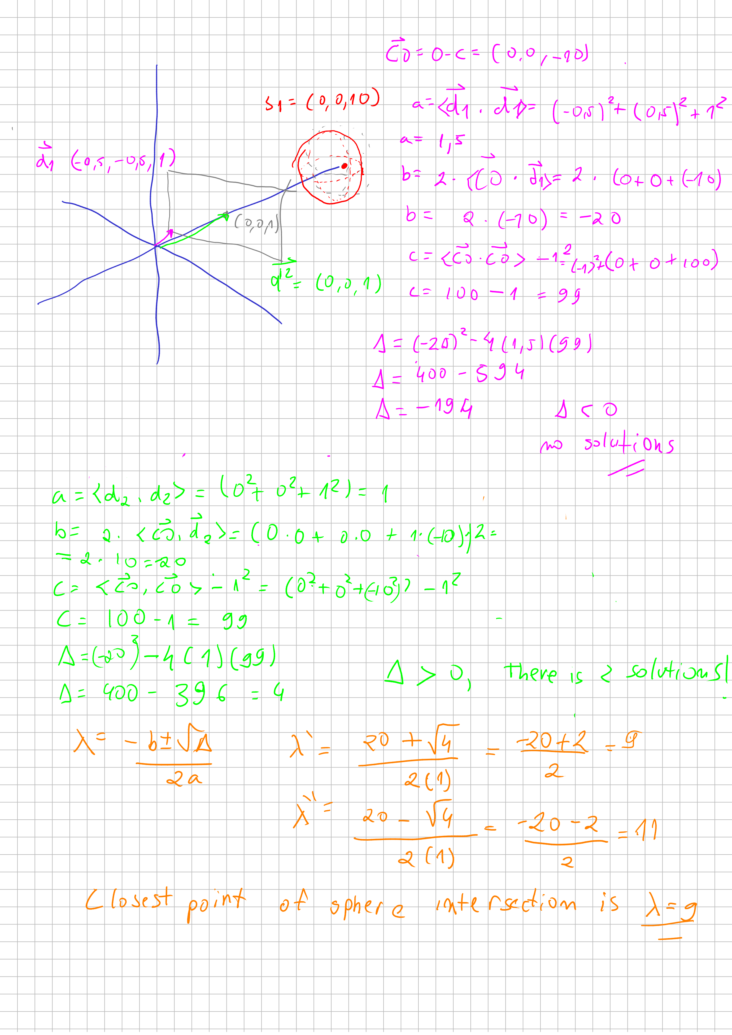
Let’s calculate if our equations make sense!
Let’s code this !
I’m going to implement this raytracing algorithm in javascript. But you could follow it up in any particular language. So you notice that the only thing we going to draw for now it’s just the circunference of the sphere. Without proper lighting and ilumintation.
So let’s see our pseudo-code top-down. Lets start from the global method to compute each pixel and specializing the functions until we reach our ray-sphere computation.
for each pixel at the screen:
	pixel_at_world_coordinate = map pixel position to projection plane position
	hit_object <= cast_ray at pixel_at_world_coordinate

	if hit_object is not null:
		pixel color <= hit_object.color
	else:
		pixel color <= background.color
This procedure we going to for each pixel, map the screen position to our “plane” position. Then we cast a ray from origin through our plane position. If we intersect anything, we want to color the particular pixel with that color else we going to paint with background color.
Our procedure that control our cast_ray() is going to call the intersection with spheres, planes, triangles. But for now we only have spheres.
So our procedure for ray_casting() will be something like this:
Because our program still a simple one, our camera doesnt move. Therefore we going to set a global variable PLANE_DISTANCE <= 1 so we know that the solution is in front of our projection plane.
cast_ray (direction, world) :
	let closest_sphere <= <sphere: null, distance: infinity>

	for each sphere in world:
		let [solution1, solution2] <= intersect_sphere(direction, sphere)

		if solution1 < closest_sphere.distance and solution1 > PLANE_DISTANCE:
			closest_sphere <= < sphere, distance: solution1 >
		else if solution2 < closest_sphere.distance and solution2 > PLANE_DISTANCE:
			closest_sphere <= < sphere, distance: solution2 >

	if closest_sphere.sphere is null:
		return null

	return closest_sphere.sphere
Our raycasting method only cast rays to spheres for now. And just checks for the closest solution if any.
Finally, let’s compute if there is any solution: Which is just implement bhaskara equation and returning the solutions based on the vectors computations.
interset_sphere(direction, sphere):
	let center_to_origin <= origin - sphere.center

	let a <= direction.dot(direction)
	let b <= 2 * center_to_origin.dot(direction)
	let c <= center_to_origin.dot(center_to_origin) - sphere.radius * sphere.radius

	let delta = b * b - 4 * a * c;

	if delta < 0:
		return [infinity, infinity]
	else:
		let solution1 <= (-b + sqrt(delta) ) 2* a
		let solution2 <= (-b - sqrt(delta) ) 2* a
		return [solution1, solution2]
And that my friends, should do the trick to render a circle in your screen:
// a basic Vector class
export class Vector3f {
  constructor(x, y, z) {
    this.x = x;
    this.y = y;
    this.z = z;
  }

  dot(vector) {
    return this.x * vector.x + this.y * vector.y + this.z * vector.z;
  }

  add(vector) {
    return new Vector3f(
      this.x + vector.x,
      this.y + vector.y,
      this.z + vector.z
    );
  }
  sub(vector) {
    return new Vector3f(
      this.x - vector.x,
      this.y - vector.y,
      this.z - vector.z
    );
  }
}


// the code !

import { Vector3f } from "./vector.js";

// simple html canvas.
// reference to canvas: https://developer.mozilla.org/pt-BR/docs/Web/API/Canvas_API/Tutorial
const canvas = document.getElementById("canvas");
const context = canvas.getContext("2d");

const width = canvas.width;
const height = canvas.height;

const canvasBuffer = context.getImageData(0, 0, width, height);

// this is our "world"
const world = {
  spheres: [
    {
      center: new Vector3f(0, 0, 7),
      radius: 1,
      color: { r: 255, g: 0, b: 0, a: 255 },
    },
  ],
};


/*
The blit function is a commom function to graphics libs.
It usually just takes a pixel buffer, and put on the screen. And that's
exactly what this blit function does
*/
const blit = () => {
  context.putImageData(canvasBuffer, 0, 0);
};


const canvasPixel = (x, y, r, g, b, a) => {
  const index = (x + y * width) * 4;
  canvasBuffer.data[index + 0] = r;
  canvasBuffer.data[index + 1] = g;
  canvasBuffer.data[index + 2] = b;
  canvasBuffer.data[index + 3] = a;
};

/*
Our putPixel accepts cartesian coordinates and translate's it to our screen coordinates.
Just like in the begining of the text!
*/
const putPixel = (x, y, color) => {
  let canvasX = width / 2 + x;
  let canvasY = height / 2 - y;

  canvasPixel(canvasX, canvasY, color.r, color.g, color.b, color.a);
};

/*
This is our function to map our cartesian coordinate to our projection plane position
*/
const mapScreenToWorldPlane = (x, y) => {
  let updateX = x / width;
  let updateY = y / height;
  return [updateX, updateY];
};

const intersectSphere = (direction, sphere) => {
  let centerToOrigin = new Vector3f(0, 0, 0).sub(sphere.center);

  let a = direction.dot(direction);
  let b = 2 * centerToOrigin.dot(direction);
  let c = centerToOrigin.dot(centerToOrigin) - sphere.radius ** 2;

  let delta = b ** 2 - 4 * a * c;

  if (delta < 0) {
    return [Infinity, Infinity];
  }

  let sol1 = (-b + Math.sqrt(delta)) / (2 * a);
  let sol2 = (-b - Math.sqrt(delta)) / (2 * a);
  return [sol1, sol2];
};

const traceRay = (direction, world) => {
  let closestSphere = { sphere: null, distance: Infinity };

  world.spheres.forEach((sphere) => {
    let [sol1, sol2] = intersectSphere(direction, sphere);

    if (sol1 < closestSphere.distance && sol1 > 1) {
      closestSphere = { sphere: sphere, distance: sol1 };
    } else if (sol2 < closestSphere.distance && sol2 > 1) {
      closestSphere = { sphere: sphere, distance: sol2 };
    }
  });

  if (closestSphere.sphere === null) return false;
  return closestSphere.sphere;
};

for (let x = -width / 2; x < width / 2; x++) {
  for (let y = -height / 2; y < height / 2; y++) {
    let [xWorld, yWorld] = mapScreenToWorldPlane(x, y);
    const direction = new Vector3f(xWorld, yWorld, 1);

    const hit = traceRay(direction, world);
    if (hit) {
      putPixel(x, y, hit.color);
    } else {
      putPixel(x, y, { r: 255, g: 255, b: 255, a: 255 });
    }
  }
}

blit();
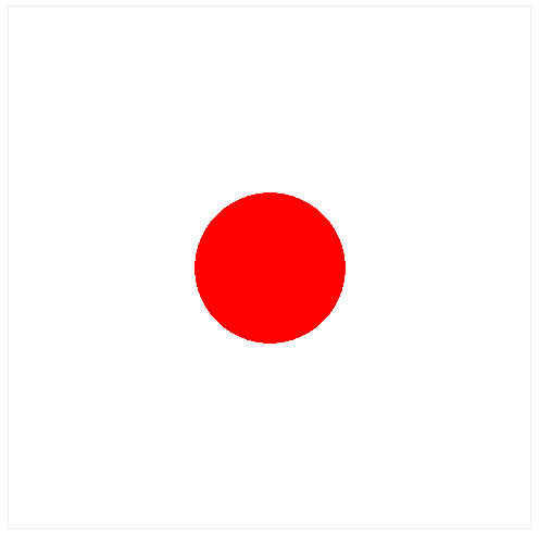
You should render this:
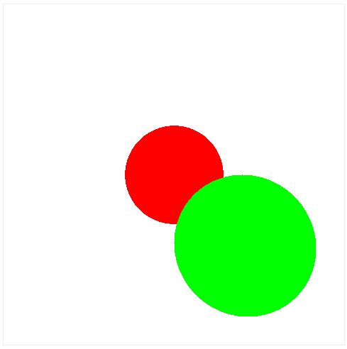
If you add another sphere, you should expect to render in front of eachother properly:
    {
      center: new Vector3f(1, -1, 7),
      radius: 1,
      color: { r: 0, g: 255, b: 0, a: 255 },
    },
What is next
Next we are going to render lighting effects. And after that we are ready to render triangles and display some tridimensional meshes like with custom shapes! See you next time!
You can access the source code here: https://github.com/lrdass/cns